Visual IoT Studio is a work in progress…. if you want to download and test it please contact with me at the contact page
First of all we need to upload an apropiated sketch to your Arduino. OPC library provides a generic sketch that publish all the input/output of an Arduino.
Please, download the latest OPC Library source from https://github.com/SoftwareTools4Makers/OPC and refer to Installing the OPC library.
At examples folder you will find an UNO example sketch that allow to use the Arduino and OPC in a simple way. You can test if all it is ok using the next link ( http://www.st4makers.com/arduino-opc-server/installation-guides/easy-testing-of-your-opc-sketch ).
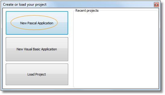
This time we are going to select New Pascal Application, but you could use VB too.
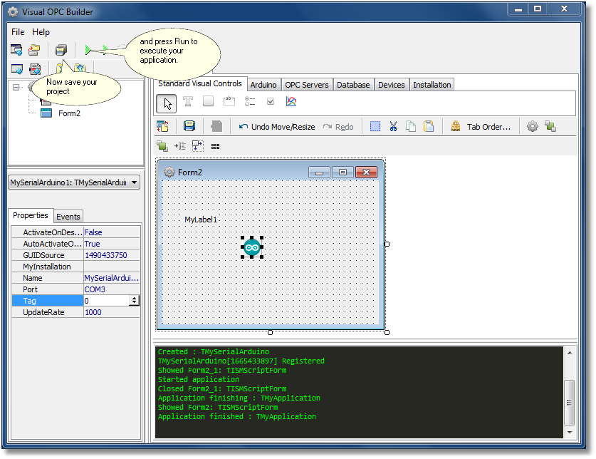
The first step is to rename you project from default. This can be done clicking and pressing over project name and use your desire project name. Your project will be saved in a directory with the same name of your project into “myprojects” folder.
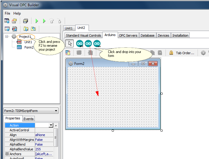
Once renamed you can start to drop your components into your application. You can drop an Arduino component and a Label component in your form. It is important for you to set the apropiated serial port into your Arduino component properties.
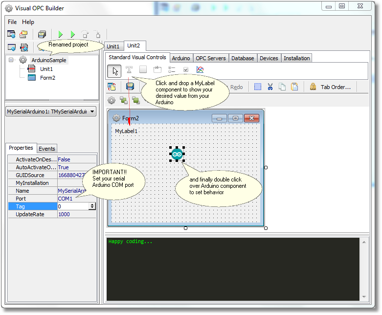
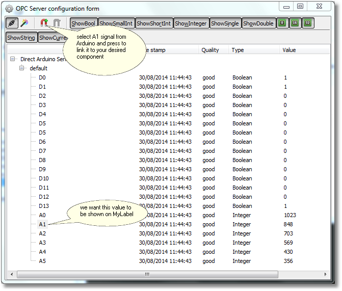
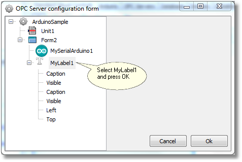
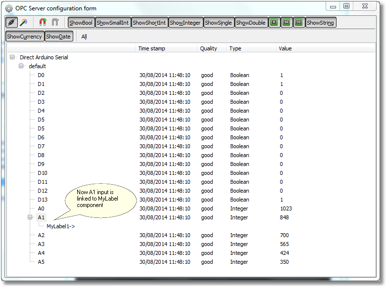
Double click your Arduino component to open the component configuration form. There you can link inputs to your visual components. This time we link an analog input with your label.
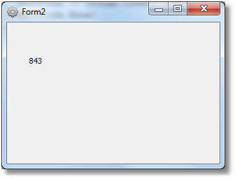
Save your project and press run to execute it. If all is ok you will see your analog value from the Arduino sketch displayed in the label.
Of course you can add more components and decorations that you want.